Vfd For 3 Phase Motor
Vfd motor phase Wired and programmed 1.5hp motor and vfd package 3 phase motor vfd circuit diagram
Using a VFD To Convert Single-Phase to Three-Phase Power (Updated
Vfd for single phase motor 3 phase motor vfd circuit diagram How to connect single phase motor to 3 phase vfd
Vfd programmed wired 5hp artisansupplies
Vfd on single phase motor[diagram] abb vfd motor starter wiring diagrams 3 phase motor and vfdUsing a vfd to convert single-phase to three-phase power (updated.
Vfd phase circuit motor diagram speed homemade ic make projects manualInspirasi 36+ inverter motor 1 phase ke 3 phase Vfd 3 phase motor wiring diagram 1 vfd 2 motors wiringWiring a vfd to a 3 phase motor.

3 phase motor vfd circuit diagram
Introduction to 3-phase motor vfds: understanding the basicsHow to control a 3-phase motor with plc & vfd Drives & motor controls 1.5kw 3ph vfd single phase motor speed controlHow to connect single phase motor to 3 phase vfd.
3 phase vfd motor control circuit diagramWiring 3 phase motor to vfd Vfd input 1336 convert telemetry wires frequency 240vacHow to make a 3 phase vfd circuit.

Phase vfd inverter three frequency kw ato converter 5hp inspirasi ke 3hp 2kw input sumber
How to select the right 3-phase motor vfd for your applicationIndustry automation blog: how to wire 3 phase motor to vfd Vfd 3 phase motor wiring diagram 1 vfd 2 motors wiringVfd for single phase motor.
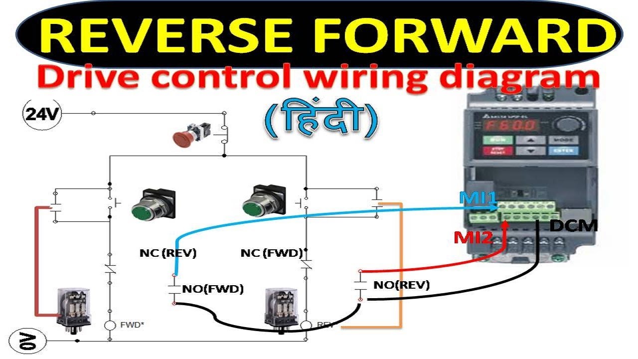
Vfd vfds input rural facilitiesHow to reverse and forward a 3-phase motor using vfd? Vfd motor wiring diagram vfd wiring diagram el delta question controlPhase vfd single motor.
1.5kw 380v 3 phase vfd variable frequency inverter motor drive speed c
Brake wiring 3 phase motor vfdControlling 3 phase induction motor using vfd and plc How to use vfd inverter for 3 phase motorOn video motor connection with vfd wiring diagram.
Vfd plc induction controlling wiring electronicsforu inverter motors connecting electrical waveforms waveform circuitsVfds and single phase power Three phase motor on through single phase vfd .bs electrical3 phase motor vfd circuit diagram.

Wiring vfd motor phase gorton mill wire 2011 power automation industry am vb practicalmachinist
Variable frequency drive 3 phase .
.


Using a VFD To Convert Single-Phase to Three-Phase Power (Updated

How to Make a 3 Phase VFD Circuit - Homemade Circuit Projects

Wired and Programmed 1.5HP Motor and VFD Package - Artisan Supplies

How to control a 3-phase motor with PLC & VFD | Delay program

Drives & Motor Controls 1.5KW 3PH VFD Single Phase Motor Speed Control

3 Phase Motor Vfd Circuit Diagram

3 Phase Motor Vfd Circuit Diagram